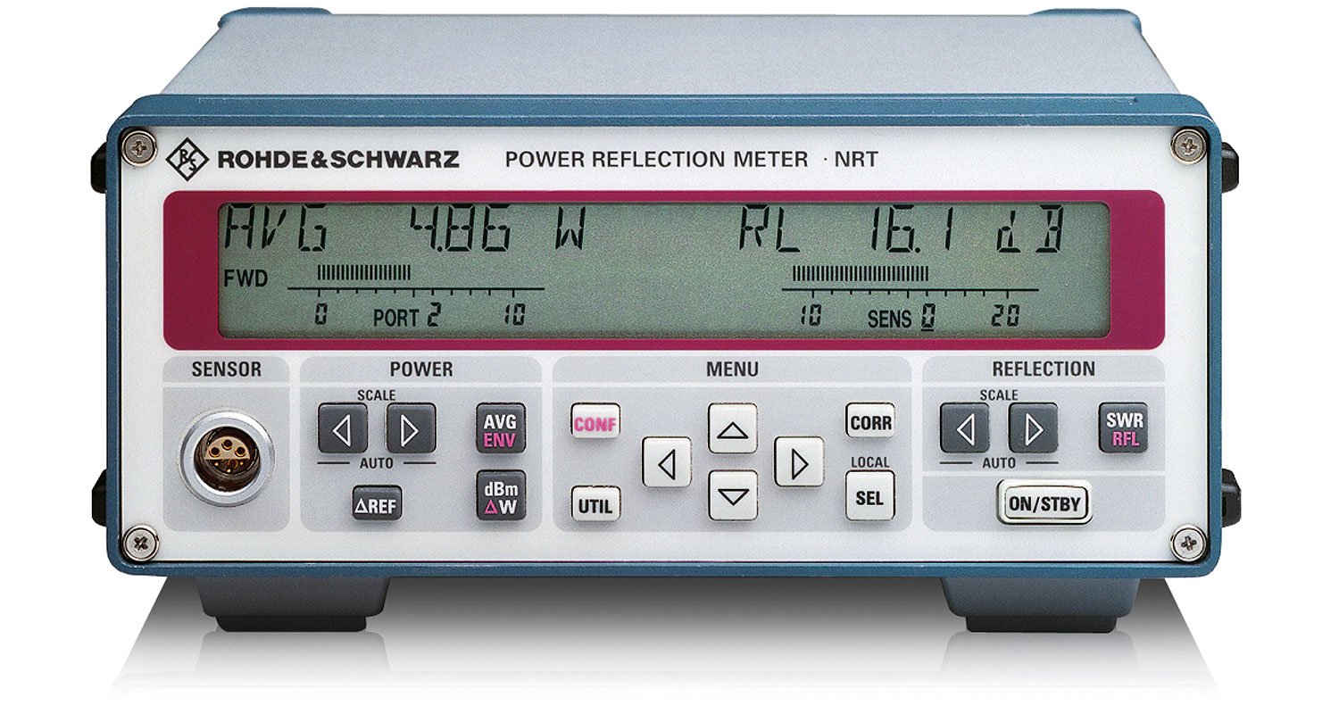
Rohde & Schwarz NRT Power Reflection Meter
Manufacturer: Rohde & Schwarz
Model Number: NRT
Directional power meters are used to measure power and reflection under operational conditions. They are connected between source and load and measure the power flow in both directions. The power applied to the load and the reflection can thus be measured. Typical applications are in installation, maintenance and monitoring of amplifiers, transmitters, antennas and RF/microwave generators in industrial and medical fields.
- Power measurement on transmitters, amplifiers, industrial RF and microwave generators
- Simultaneous display of power and reflection
- Measurement of average power irrespective of modulation mode
- Measurement of peak power, crest factor and average burst power
- Compatible with all main digital standards, for example, GSM/EDGE, 3GPP (W-/TD-CDMA), CDMA (IS-95), CDMA2000, PHS, NADC, PDC, TETRA, DECT, DAB, DVB-T
- Intelligent sensors: simply plug in and go
- IEC625 (IEEE488) bus and RS-232 interface
- Digital interface between sensor and basic unit
- Direct connection of sensor to a PC
Features
- Frequency range: 200 kHz to 4 GHz
- Power measurement range: 0.7 mW to 2 kW
- Measurement inputs
- For R&S®NRT-Z sensors: 1 to 3 (4), one active one input on front panel, two additional inputs on rear panel (option R&S®NRT-B2)
- For R&S®NAP-Z sensors: one input on rear panel (option R&S®NRT-B1)
- Measurement functions
- Power: Forward power and power absorbed by the load in W, dBm, dB or % (dB and % referenced to measured value or reference value)
- Power parameters: Average power, average burst power, peak envelope power, peak-to-average ratio (crest factor), complementary cumulative distribution function
- Reflection: SWR, return loss, reflection coefficient, reverse-to-forward power ratio in %, reverse power
- Frequency response correction: Upon input of RF frequency, the stored correction factors of the power sensor being taken into account; for R&S®NAP-Z sensors the R&S®NRT base unit offers memory for 3 sets of calibration factors
- Zero adjustment: Selectable with RF power switched off, duration approximately 5 s
- LCD display
- Digital: Simultaneous indication of power, reflection, and carrier frequency (input value)
- Resolution: HIGH is 4½ digits (0.001 dB), LOW is 3½ digits (0.01 dB)
- Analog: Two 50-element bargraphs for indication of power and reflection with selectable or pre-defined scale-end values
- Averaging: Automatic, depending on selected resolution and sensor characteristics
- Max/Min: Display of current maximum, minimum, or difference value (Max-Min) for the selected measurement functions
- Remote control: To SCPI-1995.0 command set
- IEC / IEEE bus: To IEC 625 (IEEE 488); interface functions SH1, AH1, T6, L4, SR1, RL1, PP1, DC1, DT1
- Serial interface 9-pin: D-Sub connector to EIA-232E; 1200 / 2400 / 4800 / 9600 baud; RTS/CTS or XON/XOFF handshake selectable
- AUX connector: BNC connector as signaling output or trigger input (TTL)
- Beeper: For SWR monitoring (power and SWR threshold selectable) and acoustic echoing of keystrokes
- Setups: Last setting, default setting and up to four user-defined instrument settings